OpenGL 2 pipeline
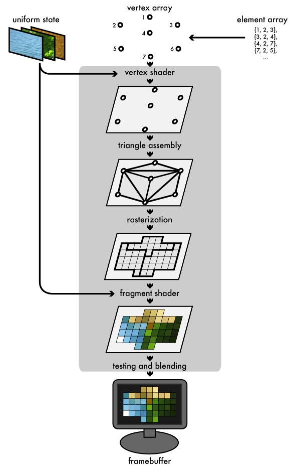
The typical task of an OpenGL program is to take as input some 3D geometry and other parameters, and render it by setting the color value for each pixel in the application window. This involves a series of transformations between spaces, and different kinds of programming tasks at each stage of the transformation. Some of the earlier steps of these operations occur on the computer’s CPU, while the later operations occur on the graphics hardware (GPU). The flow of data through this process is almost always unidirectional, hence it is sometimes called the ‘rendering pipeline’.
The host program fills OpenGL-managed memory buffers with arrays of vertices; these vertices are projected into screen space, assembled into triangles, and rasterized into pixel-sized fragments; finally, the fragments are assigned color values and drawn to the framebuffer. Modern GPUs get their flexibility by delegating the “project into screen space” and “assign color values” stages to uploadable programs called shaders.
Shader program
At any time the GPU may have one shader program bound. Typically the shader program will contain a vertex shader and a fragment shader. These allow us to insert our own code into the rendering pipeline at the vertex transformation and fragment coloring stages.
Note that shaders can also be used in combination with OpenGL 1 immediate mode geometry, though there is less flexibility regarding vertex attributes.
Vertex shader
Each vertex in the vertex array is sent through the vertex program. The vertex program determines how to modify each vertex. At minimum, it must compute the actual position of the vertex in screen space (by setting the gl_Position variable).
Here is a simple vertex shader:
// the input position of the vertex:
attribute vec3 position;

void main() {
    gl_Position = vec4(position.x, position.y, 0., 1.);
}
Vertex shaders may make use of attributes, values that are set for each input vertex. Typical vertex attributes are position, color, normal (surface direction), texture coordinate (for applying texture mapping).
Note that the GLSL language provides support for vector types (vec2, vec3, vec4) and matrix types (mat2, mat3, mat4) in the language itself, since these are so fundamental to graphics programming.
Fragment shader
For each pixel of a rendered triangle, the fragment shader is run to compute the pixel color (by setting the gl_FragColor variable). Here is a simple fragment shader:
uniform vec3 lightcolor;

void main() {
    // paint all pixels opaque red:
    vec3 red = vec3(1, 0, 0);
    // compute pixel color by multiplying with the light color:
    vec3 color = lightcolor * red;
    // store that as the result, with an alpha (opacity) value of 1:
    gl_FragColor = vec4(color, 1);
}
A uniform is a way to pass data from the CPU to either vertex or fragment shader. Uniform data has the same value for all vertices/fragments, but can change in successive renders. References to textures are also passed as uniforms (of type sampler2D).
Loading, compiling, linking and using shaders requires some fiddly OpenGL code, which we have abstracted into the shader module (you can take a look inside it to see how it works):
-- load in the shader utility module:
local shader = require "shader"

-- write the GLSL code:
local vertex_code = [[
    // the input position of the vertex:
    attribute vec3 position;

    void main() {
        gl_Position = vec4(position.x, position.y, 0., 1.);
    }
]]
local fragment_code = [[
    uniform vec3 lightcolor;

    void main() {
        // paint all pixels opaque red:
        vec3 red = vec3(1, 0, 0);
        // compute pixel color by multiplying with the light color:
        vec3 color = lightcolor * red;
        // store that as the result, with an alpha (opacity) value of 1:
        gl_FragColor = vec4(color, 1);
    }
]]

-- use this GLSL code to create a new shader program:
local myshaderprogram = shader(vertex_code, fragment_code)

-- the rendering callback:
function draw()
    -- start using the shader:
    myshaderprogram:bind()
    -- set a shader uniform:
    myshaderprogram:uniform("lightcolor", 0.5, 0.5, 0.5)

    -- RENDER VERTICES HERE

    -- done using the shader:
    myshaderprogram:unbind()
end
Vertex buffers
To make use of the shader we must send some vertices. Each vertex may have a number of attributes, including location, normal, color, texture coordainates, etc. All these together make the vertex buffer.
We can also supply an additional element array, which is an array of indices into the vertex buffer specifying the order to render them. This allows us to use one vertex more than once, or even skip a vertex we don’t want to use. It determines how the vertices become triangles.
Creating and using vertex buffers requires some fiddly OpenGL code, because it can be very generic. We have abstracted the most common case into the vbo module:
-- load in the utility module for vertex buffer objects
local vbo = require "vbo"

-- create a VBO object to store vertex position and color data
-- this vbo contains 3 vertices (1 triangle):
local vertices = vbo(15)

-- set the vertex positions:
vertices[0].position:set(-1, -1, 0)
vertices[0].position:set( 1, -1, 0)
vertices[0].position:set( 0,  1, 0)


function draw()
    -- start using the shader:
    myshaderprogram:bind()
    -- set a shader uniform:
    myshaderprogram:uniform("lightcolor", 0.5, 0.5, 0.5)

    -- tell the shader_program where to find the
    -- 'position' attributes
    -- when looking in the vertices VBO:
    vertices:enable_position_attribute(myshaderprogram)

    -- render using the data in the VBO:
    vertices:draw()

    -- detach the shader_program attributes:
    vertices:disable_position_attribute(myshaderprogram)

    -- detach the shader:
    myshaderprogram:unbind()
end
